-
1 Kabelkanal
кабельный канал
Кабельным каналом называется закрытое и заглубленное (частично или полностью) в грунт, пол, перекрытие и т. п. непроходное сооружение, предназначенное для размещения в нем кабелей, укладку, осмотр и ремонт которых возможно производить лишь при снятом перекрытии.
[ПУЭ. Раздел 2]
кабельный канал
Элемент системы электропроводки, расположенный над землей или полом или в земле или в полу, открытый, вентилируемый или замкнутый, размеры которого не позволяют вход людей, но обеспечивают доступ к трубам и (или) кабелям по всей длине в процессе монтажа и после него.
Примечание - Кабельный канал может составлять или не составлять часть конструкции здания
[ ГОСТ Р МЭК 60050-826-2009]
канал кабельный
Подземный непроходной канал, предназначенный для размещения электрических кабелей
[Терминологический словарь по строительству на 12 языках (ВНИИИС Госстроя СССР)]EN
cable channel
element of a wiring system above or in the ground or floor, open, ventilated or closed, and having dimensions which do not permit the entry of persons but allow access to the conduits and/or cables throughout their length during and after installation
NOTE – A cable channel may or may not form part of the building construction.
[IEV number 826-15-06]FR
caniveau, m
élément de canalisation situé au-dessus ou dans le sol ou le plancher, ouvert, ventilé ou fermé, ayant des dimensions ne permettant pas aux personnes d'y circuler, mais dans lequel les conduits ou câbles sont accessibles sur toute leur longueur, pendant et après installation
NOTE – Un caniveau peut ou non faire partie de la construction du bâtiment.
[IEV number 826-15-06]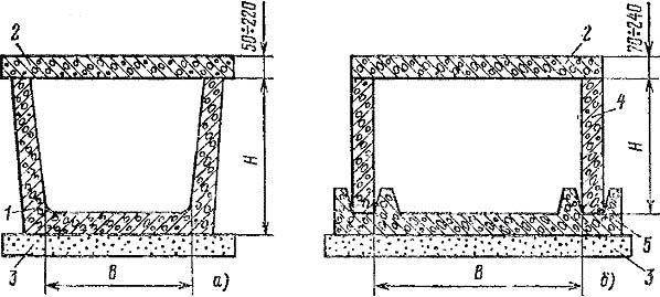
Кабельные каналы:
а — лотковый типа ЛК; б — из сборных плит типа СК:1 — лоток; 2 — плита перекрытия; 3 — подготовка; 4 — плита стеновая; 5 — основание
Высота кабельных каналов в свету не ограничивается, но бывает не более 1200 мм. Ширина каналов определяется в зависимости от размеров применяемых кабельных конструкций из условия сохранения прохода не менее 300 мм при глубине канала до 600 мм, 450 мм — от более 600 до 900 мм, 600 мм при более 900 мм.
Полы в каналах выполняют с уклоном не менее 0,5% в сторону водосборников или ливневой канализации.
Для крепления кабельных конструкций в стенах каналов через каждые 0,8—1 м (по длине) устанавливают закладные детали. При заводском изготовлении стеновых панелей детали устанавливают на предприятии-изготовителе. Закладные детали в каналах глубиной до 600 мм располагают в один ряд, при большей глубине каналов — в два ряда.
В местах поворота и разветвления трассы устраивают уширительные камеры, размеры которых выбирают с учетом допускаемого радиуса изгиба прокладываемого кабеля.
[ http://forca.ru/knigi/oborudovanie/priemka-zdaniy-i-sooruzheniy-pod-montazh-elektrooborudovaniya-11.html]Недопустимые, нерекомендуемые
Примечание(1)- Мнение автора карточкиТематики
- кабели, провода...
- электропроводка, электромонтаж
- электроустановки
Обобщающие термины
EN
- cable channel
- cable duct
- cable trench
- cabling
- conduit
- duct
- electric raceway
- raceway
- trench for cabling
DE
FR
- caniveau du câble
- caniveau, m
- conduite du câble
Немецко-русский словарь нормативно-технической терминологии > Kabelkanal
-
2 Kabelkanal, m
кабельный туннель
Коридор, размеры которого допускают проход людей по всей его длине, содержащий поддерживающие конструкции для кабелей, а также соединительные и (или) другие элементы электропроводок
[ ГОСТ Р МЭК 60050-826-2009]
кабельный туннель
Кабельным туннелем называется закрытое сооружение (коридор) с расположенными в нем опорными конструкциями для размещения на них кабелей и кабельных муфт, со свободным проходом по всей длине, позволяющим производить прокладку кабелей, ремонты и осмотры кабельных линий.
[ПУЭ. Раздел 2 ]EN
cable channel
element of a wiring system above or in the ground or floor, open, ventilated or closed, and having dimensions which do not permit the entry of persons but allow access to the conduits and/or cables throughout their length during and after installation
NOTE – A cable channel may or may not form part of the building construction.
[IEV number 826-15-06]FR
caniveau, m
élément de canalisation situé au-dessus ou dans le sol ou le plancher, ouvert, ventilé ou fermé, ayant des dimensions ne permettant pas aux personnes d'y circuler, mais dans lequel les conduits ou câbles sont accessibles sur toute leur longueur, pendant et après installation
NOTE – Un caniveau peut ou non faire partie de la construction du bâtiment.
[IEV number 826-15-06]Кабельный туннель – это подземное сооружение (коридор) с расположенными в нем опорными конструкциями для размещения на них кабелей и муфт, позволяющее производить прокладку, ремонты и осмотры со свободным проходом по всей длине.
КТ сооружают из сборного ж/б и снаружи покрывают гидроизоляцией. Заглубление – 0,5 м.
Проходы в кабельных туннелях, как правило, должны быть не менее 1 м, однако допускается уменьшение проходов до 800 мм на участках длиной не более 500 мм.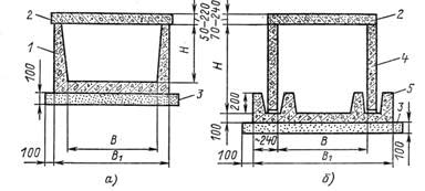
Сборные железобетонные кабельные туннели:
а – лотковые типа ЛК; б – из сборных плит типа СК;
1 – лоток;
2 – плита перекрытия;
3 – подготовка песчаная;
4 – плита;
5 – основание.
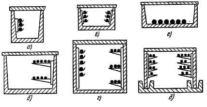
Варианты прокладки кабелей в кабельных туннелях:
а – расположение кабелей на одной стенке на подвесках;
б – то же на полках;
в – то же на обеих стенках на подвесах;
г – то же на одной стенке на подвесах, на другой на полках;
д – то же на обеих стенках на полках;
е – то же на дне туннеляПол туннеля должен быть выполнен с уклоном не менее 1 % в сторону водосборников или ливневой канализации. При отсутствии дренажного устройства через каждые 25 м должны быть устроены водосборные колодцы размером 0,4 х 0,4 х 0,3 м, перекрываемые металлическими решетками. При необходимости перехода с одной отметки на другую должны быть устроены пандусы с уклоном не более 15°.
В туннелях должна быть предусмотрена защита от попадания грунтовых и технологических вод и обеспечен отвод почвенных и ливневых вод.
Туннели должны быть обеспечены в первую очередь естественной вентиляцией. Выбор системы вентиляции и расчет вентиляционных устройств производятся на основании тепловыделений, указанных в строительных заданиях. Перепад температуры между поступающим и удаляемым воздухом в туннеле не должен превышать 10 ºС. Вентиляционные устройства должны автоматически отключаться, а воздуховоды снабжаться заслонками с дистанционным или ручным управлением для прекращения доступа воздуха в туннель в случае возникновения пожара.
В туннеле должны быть предусмотрены стационарные средства для дистанционного и автоматического пожаротушения. Источником возникновения пожара могут быть кабели, соединительные кабельные муфты. К пожару может привести небрежное обращение с огнем и легко воспламеняющимися материалами при монтажных или ремонтных работах. Выбор пожарогасящих средств производится специализированной организацией.
В туннелях должны быть установлены датчики, реагирующие на появление дыма и повышение температуры окружающей среды выше 50 °С. Коллекторы и туннели должны быть оборудованы электрическим освещением и сетью питания переносных светильников и инструмента.
Протяженные кабельные туннели разделяют по длине огнестойкими перегородками на отсеки длиной не более 150 м с устройством в них дверей шириной не менее 0,8 м. Двери из крайних отсеков должны открываться в помещение или наружу. Дверь в помещение должна открываться ключом с двух сторон. Наружная дверь должна быть снабжена самозакрывающимся замком, открывающимся ключом снаружи. Двери в средних отсеках должны открываться в сторону лестницы и быть снабжены устройствами, фиксирующими их закрытое положение. Открываются эти двери с обеих сторон без ключа.
Прокладка кабелей в коллекторах и туннелях рассчитывается с учетом возможности дополнительной прокладки кабелей в количестве не менее 15 %.
Силовые кабели напряжением до 1 кВ следует прокладывать под кабелями напряжением выше 1 кВ и разделять их горизонтальной перегородкой. Различные группы кабелей, а именно рабочие и резервные напряжением выше 1 кВ, рекомендуется прокладывать на разных полках с разделением их горизонтальными несгораемыми перегородками. В качестве перегородок рекомендуются асбоцементные плиты, прессованные неокрашенные тол-щиной не менее 8 мм. Прокладку бронированных кабелей всех сечений и небронированных сечением жил 25 мм2 и выше следует выполнять по конструкциям (полкам), а небронированных кабелей сечением жил 16 мм2 и менее – на лотках, уложенных на кабельные конструкции.
Кабели, проложенные в туннелях, должны быть жестко закреплены в конечных точках, с обеих сторон изгибов и у соединительных муфт.
Во избежание установки дополнительных соединительных муфт следует выбирать строительную длину кабелей.
Каждую соединительную муфту на силовых кабелях нужно укладывать на отдельной полке опорных конструкций и заключать в защитный противопожарный кожух, который должен быть отделен от верхних и нижних кабелей по всей ширине полок защитными асбоцементными перегородками. В каждом туннеле и канале необходимо предусмотреть свободные ряды полок для укладки соединительных муфт.
Для прохода кабелей через перегородки, стены и перекрытия должны быть установлены патрубки из несгораемых труб.
В местах прохода кабелей в трубах зазоры в них должны быть тщательно уплотнены несгораемым материалом. Материал заполнения должен обеспечивать схватывание и легко поддаваться разрушению в случае прокладки дополнительных кабелей или их частичной замены.
Небронированные кабели с пластмассовой оболочкой допускается крепить скобами (хомутами) без прокладок.
Металлическая броня кабелей, прокладываемых в туннелях, должна иметь антикоррозионное покрытие. Расстояние между полками кабельных конструкций при прокладке силовых кабелей напряжением до 10 кВ должно быть не менее 200 мм. Расстояние между полками при установке огнестойкой перегородки при прокладке кабелей должно быть не менее 200 мм, а при укладке соединительной муфты 250 или 300 мм – в зависимости от типоразмера муфты.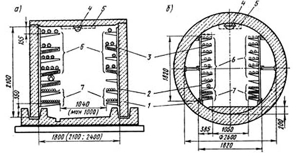
Расположение кабелей в туннеле:
а – туннель прямоугольного сечения; б – туннель круглого сечения;
1 – блок туннеля;
2 – стойка;
3 – полка;
4 – светильник;
5 – зона пожароизвещателей и трубопроводов механизированной уборки пыли и пожаротушения;
6 – силовые кабели;
7 – контрольные кабели
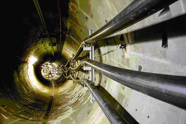
Кабельный туннель круглого сечения
Тематики
- электропроводка, электромонтаж
- электроустановки
Обобщающие термины
EN
DE
- Kabelkanal, m
FR
- caniveau, m
Немецко-русский словарь нормативно-технической терминологии > Kabelkanal, m
-
3 Dauerstrombelastbarkeit, f
(длительный) допустимый ток
Максимальное значение электрического тока, который может протекать длительно по проводнику, устройству или аппарату при определенных условиях без превышения определенного значения их температуры в установившемся режиме
[ ГОСТ Р МЭК 60050-826-2009]
Этот ток обозначают IZ
[ ГОСТ Р 50571. 1-2009 ( МЭК 60364-1: 2005)]EN
(continuous) current-carrying capacity
ampacity (US)
maximum value of electric current which can be carried continuously by a conductor, a device or an apparatus, under specified conditions without its steady-state temperature exceeding a specified value
[IEV number 826-11-13]
ampacity
The current in amperes that a conductor can carry continuously under the conditions of use without exceeding its temperature rating.
[National Electrical Cod]FR
courant (permanent) admissible, m
valeur maximale du courant électrique qui peut parcourir en permanence, un conducteur, un dispositif ou un appareil, sans que sa température de régime permanent, dans des conditions données, soit supérieure à la valeur spécifiée
[IEV number 826-11-13]Ampacity, the term is defined as the maximum amount of current a cable can carry before sustaining immediate or progressive deterioration. Also described as current rating or current-carrying capacity, is the RMS electric current which a device can continuously carry while remaining within its temperature rating. The ampacity of a cable depends on:
- its insulation temperature rating;
- conductor electrical properties for current;
- frequency, in the case of alternating currents;
- ability to dissipate heat, which depends on cable geometry and its surroundings;
- ambient temperature.
Electric wires have some resistance, and electric current flowing through them causes voltage drop and power dissipation, which heats the cable. Copper or aluminum can conduct a large amount of current before melting, but long before the conductors melt, their insulation would be damaged by the heat.
The ampacity for a power cable is thus based on physical and electrical properties of the material & construction of the conductor and of its insulation, ambient temperature, and environmental conditions adjacent to the cable. Having a large overall surface area may dissipate heat well if the environment can absorb the heat.
In a long run of cable, different conditions govern, and installation regulations normally specify that the most severe condition along the run governs the cable's rating. Cables run in wet or oily locations may carry a lower temperature rating than in a dry installation. Derating is necessary for multiple circuits in close proximity. When multiple cables are near, each contributes heat to the others and diminishes the amount of cooling air that can flow past the individual cables. The overall ampacity of the insulated conductors in a bundle of more than 3 must be derated, whether in a raceway or cable. Usually the de-rating factor is tabulated in a nation's wiring regulations.
Depending on the type of insulating material, common maximum allowable temperatures at the surface of the conductor are 60, 75 and 90 degrees Celsius, often with an ambient air temperature of 30°C. In the U.S., 105°C is allowed with ambient of 40°C, for larger power cables, especially those operating at more than 2 kV. Likewise, specific insulations are rated 150, 200 or 250°C.
The allowed current in cables generally needs to be decreased (derated) when the cable is covered with fireproofing material.
For example, the United States National Electric Code, Table 310-16, specifies that up to three 8 AWG copper wires having a common insulating material (THWN) in a raceway, cable, or direct burial has an ampacity of 50 A when the ambient air is 30°C, the conductor surface temperature allowed to be 75°C. A single insulated conductor in air has 70 A rating.
Ampacity rating is normally for continuous current, and short periods of overcurrent occur without harm in most cabling systems. The acceptable magnitude and duration of overcurrent is a more complex topic than ampacity.
When designing an electrical system, one will normally need to know the current rating for the following:- Wires
- Printed Circuit Board traces, where included
- Fuses
- Circuit breakers
- All or nearly all components used
Some devices are limited by power rating, and when this power rating occurs below their current limit, it is not necessary to know the current limit to design a system. A common example of this is lightbulb holders.
[http://en.wikipedia.org/wiki/Ampacity]
Тематики
- электротехника, основные понятия
Синонимы
EN
DE
- Dauerstrombelastbarkeit, f
- Strombelastbarkeit, f
FR
- courant admissible, m
- courant permanent admissible, m
Немецко-русский словарь нормативно-технической терминологии > Dauerstrombelastbarkeit, f
-
4 Strombelastbarkeit, f
(длительный) допустимый ток
Максимальное значение электрического тока, который может протекать длительно по проводнику, устройству или аппарату при определенных условиях без превышения определенного значения их температуры в установившемся режиме
[ ГОСТ Р МЭК 60050-826-2009]
Этот ток обозначают IZ
[ ГОСТ Р 50571. 1-2009 ( МЭК 60364-1: 2005)]EN
(continuous) current-carrying capacity
ampacity (US)
maximum value of electric current which can be carried continuously by a conductor, a device or an apparatus, under specified conditions without its steady-state temperature exceeding a specified value
[IEV number 826-11-13]
ampacity
The current in amperes that a conductor can carry continuously under the conditions of use without exceeding its temperature rating.
[National Electrical Cod]FR
courant (permanent) admissible, m
valeur maximale du courant électrique qui peut parcourir en permanence, un conducteur, un dispositif ou un appareil, sans que sa température de régime permanent, dans des conditions données, soit supérieure à la valeur spécifiée
[IEV number 826-11-13]Ampacity, the term is defined as the maximum amount of current a cable can carry before sustaining immediate or progressive deterioration. Also described as current rating or current-carrying capacity, is the RMS electric current which a device can continuously carry while remaining within its temperature rating. The ampacity of a cable depends on:
- its insulation temperature rating;
- conductor electrical properties for current;
- frequency, in the case of alternating currents;
- ability to dissipate heat, which depends on cable geometry and its surroundings;
- ambient temperature.
Electric wires have some resistance, and electric current flowing through them causes voltage drop and power dissipation, which heats the cable. Copper or aluminum can conduct a large amount of current before melting, but long before the conductors melt, their insulation would be damaged by the heat.
The ampacity for a power cable is thus based on physical and electrical properties of the material & construction of the conductor and of its insulation, ambient temperature, and environmental conditions adjacent to the cable. Having a large overall surface area may dissipate heat well if the environment can absorb the heat.
In a long run of cable, different conditions govern, and installation regulations normally specify that the most severe condition along the run governs the cable's rating. Cables run in wet or oily locations may carry a lower temperature rating than in a dry installation. Derating is necessary for multiple circuits in close proximity. When multiple cables are near, each contributes heat to the others and diminishes the amount of cooling air that can flow past the individual cables. The overall ampacity of the insulated conductors in a bundle of more than 3 must be derated, whether in a raceway or cable. Usually the de-rating factor is tabulated in a nation's wiring regulations.
Depending on the type of insulating material, common maximum allowable temperatures at the surface of the conductor are 60, 75 and 90 degrees Celsius, often with an ambient air temperature of 30°C. In the U.S., 105°C is allowed with ambient of 40°C, for larger power cables, especially those operating at more than 2 kV. Likewise, specific insulations are rated 150, 200 or 250°C.
The allowed current in cables generally needs to be decreased (derated) when the cable is covered with fireproofing material.
For example, the United States National Electric Code, Table 310-16, specifies that up to three 8 AWG copper wires having a common insulating material (THWN) in a raceway, cable, or direct burial has an ampacity of 50 A when the ambient air is 30°C, the conductor surface temperature allowed to be 75°C. A single insulated conductor in air has 70 A rating.
Ampacity rating is normally for continuous current, and short periods of overcurrent occur without harm in most cabling systems. The acceptable magnitude and duration of overcurrent is a more complex topic than ampacity.
When designing an electrical system, one will normally need to know the current rating for the following:- Wires
- Printed Circuit Board traces, where included
- Fuses
- Circuit breakers
- All or nearly all components used
Some devices are limited by power rating, and when this power rating occurs below their current limit, it is not necessary to know the current limit to design a system. A common example of this is lightbulb holders.
[http://en.wikipedia.org/wiki/Ampacity]
Тематики
- электротехника, основные понятия
Синонимы
EN
DE
- Dauerstrombelastbarkeit, f
- Strombelastbarkeit, f
FR
- courant admissible, m
- courant permanent admissible, m
Немецко-русский словарь нормативно-технической терминологии > Strombelastbarkeit, f
-
5 Steckdose
гнездо
-
[IEV number 151-12-20]EN
socket
connector attached to an apparatus, or to a constructional element or alike
NOTE – Contact members of a socket may be socket contacts, pin contacts or both.
[IEV number 151-12-20]FR
socle, m
embase, f
connecteur fixé à un appareil ou à un élément de construction ou analogue
NOTE – Les éléments de contact d’un socle peuvent être des contacts femelles aussi bien que des contacts mâles.
[IEV number 151-12-20]Тематики
EN
DE
FR
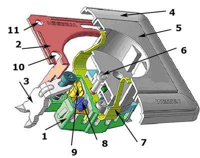
розетка
Часть соединителя, имеющая контакты для соединения со штырями вилки и контактные зажимы для присоединения кабеля, шнура или провода.
[ ГОСТ Р 51322.1-99]
розетка
-
[IEV number 442-03-02]EN
socket-outlet
an accessory having socket-contacts designed to engage with the pins of a plug and having terminals for the connection of cables or cords
[IEV number 442-03-02]FR
socle de prise de courant
appareil pourvu de contacts de socle conçus pour recevoir les broches d'une fiche et pourvu de bornes pour la connexion de conducteurs
[IEV number 442-03-02]1 - основание механизма;
2 - суппорт;
3 - распорная лапка;
4 - рамка, (декоративная рамка, монтажная рамка);
5 - верхняя часть розетки (лицевая панель);
6 - винт крепления;
7 - боковой заземляющий контакт;
8 - винтовой зажим крепления провода;
9 - гнездовой контакт;
10, 11 - отверстия для крепления суппорта винтами к монтажной коробкеТематики
EN
DE
FR
розеточная часть электрического соединителя
Часть электрического соединителя с гнездовыми контактами
[ ГОСТ 21962-76]
гнездо
[IEV number 151-12-20]EN
socket
the female part of a two part connector
[IEC 60874-1, ed. 5.0 (2006-10)]
[IEC 61274-1, ed. 2.0 (2007-04)]
socket
connector attached to an apparatus, or to a constructional element or alike
NOTE – Contact members of a socket may be socket contacts, pin contacts or both.
[IEV number 151-12-20]
socket-outlet
accessory having socket-contacts designed to engage with the pins of a plug and having terminals for the connection of cable
[IEC 60884-1, ed. 3.0 (2002-06)]
[IEC 62335, ed. 1.0 (2008-07)]FR
socle
partie femelle d’un connecteur en deux parties
[IEC 60874-1, ed. 5.0 (2006-10)]
[IEC 61274-1, ed. 2.0 (2007-04)]
socle, m
embase, f
connecteur fixé à un appareil ou à un élément de construction ou analogue
NOTE – Les éléments de contact d’un socle peuvent être des contacts femelles aussi bien que des contacts mâles
[IEV number 151-12-20]
socle
appareil pourvu d'alvéoles conçues pour recevoir les broches d'une fiche et pourvu de bornes pour la connexion d'un câble
[IEC 60884-1, ed. 3.0 (2002-06)]
[IEC 62335, ed. 1.0 (2008-07)]Внимание!
Определения по ГОСТ 21962-76 и по МЭС 151-12-20 не совпадают. Согласно МЭС 151-12-20 socket , это часть соединителя, которая присоединена к аппарату или к конструктивному элементу и может иметь в качестве контактов гнезда, штыри или и то и другое.. Таким образом, согласно МЭС 151-12-20 socket, это и приборная вилка и приборная розетка.
[Интент]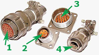
[http://www.rmdt1.narod.ru/]-
Розеточная часть электрического соединителя
- Розеточная часть электрического соединителя
-
Вилочная часть электрического соединителя
- Вилочная часть электрического соединителя
Недопустимые, нерекомендуемые
Тематики
Классификация
>>>Синонимы
EN
DE
FR
- embase, f
- socle, m
Немецко-русский словарь нормативно-технической терминологии > Steckdose
-
Розеточная часть электрического соединителя
См. также в других словарях:
Cable railings — or wire rope railings are safety rails that use horizontal or vertical cables in place of spindles, glass, mesh etc for infill. UsesThis type of railing is favored in areas where view of the landscape or ocean would be impaired by other types of… … Wikipedia
Cable — For other uses, see Cable (disambiguation). 6 inch (15 cm) outside diameter, oil cooled cables, traversing the Grand Coulee Dam throughout. An example of a heavy cable for power transmission … Wikipedia
Cable television in the Republic of Ireland — is the most common system for distributing multi channel television in the state. With a 40+ year history and extensive networks of both wired and wireless cable, the Republic of Ireland is amongst the most cabled countries in Europe.HistoryCable … Wikipedia
Cable television in the United States — is a common form of television delivery, generally by subscription. Cable television first became available in the United States in 1948, with subscription services in 1949. Data by SNL Kagan shows that as of 2006 about 58.4% of all American… … Wikipedia
Cable barrier — Cable barrier, sometimes referred to as guard cable, is a type of roadside or median barrier. It consists of steel wire ropes mounted on weak posts. As is the case with any roadside barrier, its primary purpose is to prevent a vehicle from… … Wikipedia
Construction of One World Trade Center — was deferred until 2006 because of disputes between port authority and the developer. Tishman Realty Construction,[1] is the selected builder. The building reached ground level on May 17, 2008 and is scheduled to be completed by the end of 2012… … Wikipedia
Construction D'une Motocyclette — La construction d une motocyclette se décompose en différentes parties détaillés ci après. Sommaire 1 Le châssis 2 Les suspensions 3 Les freins 3.1 Constitution … Wikipédia en Français
Cable London — Brief history Cable London plc was the operating name and brand of a cable telecommunications company that operated in five north London boroughs from the 1980s until the company was purchased by Telewest in 1999. Following the privatisation in… … Wikipedia
Cable-stayed bridge — BridgeTypePix image title=The Rio Antirio bridge in Greece type name=Cable stayed bridge sibling names=None descendent names=Side spar cable stayed bridge, Self anchored suspension bridge, cantilever spar cable stayed bridge ancestor… … Wikipedia
Cable Cars de San Francisco — 37° 47′ 44″ N 122° 24′ 27″ W / 37.79555556, 122.4075 … Wikipédia en Français
Cable television — CATV redirects here. For CAT5 cable, see Category 5 cable. Coaxial cable is often used to transmit cable television into a residence. Cable television is a system of providing television programs to consumers via radio frequency (RF) signals… … Wikipedia